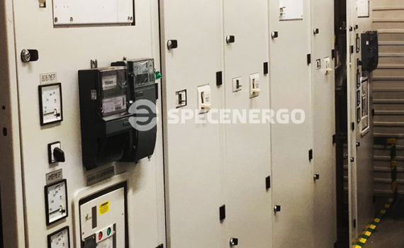
Low-voltage switchgear cabinets (LVSG) are intended for completing the panels for receiving and distributing the electrical energy, as well as for the protection against overloads and short-circuit currents in three-phase electrical grids with dead-earthed neutral in four-wire and five-wire versions of three-phase alternating current with a frequency of 50 Hz and voltage up to 1000 V.
LVSG are used in the power supply systems of agricultural facilities, oil and gas fields, residential buildings, individual settlements, industrial enterprises and intrashop substations.

LVSG distinguishing features
- The product maximum factory readiness.
- Ability to install various types and composition of equipment in accordance with the Customer’s requirements.
- Convenience of assembling and operation.
- Possibility of connection both from top and bottom sides.
LVSG operation conditions
- LVSG climatic version and placement category — Y3 in accordance with GOST 1515-69;
- Ambient air temperature from +5° C to +40° C;
- Environment is non-explosive, free of dust, including conductive dust, corrosive vapors and gases in concentrations that destroy metal and insulation;
- Operating conditions group in terms of exposure to environment according to GOST 17516.1-90 – M2;
- Air relative humidity up to 80% at the temperature of 20ºС in accordance with GOST 15543.1-89
- Installation altitude above sea level is no more than 2000m (when operating the panels at an altitude of more than 1000m, the characteristics of the devices used in the panels shall be reduced in accordance with GOST 15150-69);
- The working position in space is vertical, deviations from the vertical position up to 5° in any direction are allowed;
- Protection level of the LVSG IP31 according to GOST 14254-96;
- Seismic resistance is 6 points per MSK- 64.
LVSG completeness
The LVSG is a panel consisting of a group of cabinets of two-sided maintenance in a protected version with electrical equipment for switching, measuring, signaling, control and protection installed in them.
LVSG composition
- version: draw-out; — type: Schneider Electric, Moeller, ABB, Siemens and others.
- Presence of the COCB;
- control type: local, remote, long distance control;
- version: plugged-in and stationary;
- type: Schneider Electric, Moeller, ABB, Siemens;
- control type: local, remote is possible;
- version: plugged-in and stationary;
- type: Schneider Electric, Moeller, ABB, Siemens;
- control type: local, remote is possible;
Electronic counters of various manufacturers, which are installed on introduction leads;
Equipment of secondary switching circuits and instrumentation of foreign and Russian manufacturers: Schneider Electric, Relpol, Proton-Impulse, Electropribor, Novatek-Electro and others.
The configuration and composition of the equipment used in LVSG can be changed at the Customer’s request in accordance with the technical specification requirements.
Design features
The LVSG cell frame consists of horizontal frames and vertical posts that form a rigid and impact-resistant structure. The nuts intended for griping during lifting and relocating, to which eye-bolts are installed in the case of transportation by individual cabinets, or a transport frame is used for the LVSG transport group, are installed in the cabinet upper part.
The LVGS can include the following:
- the lowest voltage incoming line section ILS;
- the lowest voltage linear section LLS;
- the lowest voltage line emergency section ELS;
- the lowest voltage sectional section LSS;
- the lowest voltage capacitors section LCS;
- incoming line section from DPP LVS;
- control cabinet CC;
- bus bar bridge (BBB)
Each cabinet is divided into cells. The cells in the cabinet are separated from each other by steel sheet partitions. Each cell has a separate door.
The cabinets assembled in the LVSG are connected by bus bars. The cables are brought to the leads of the outgoing lines from below. Operational maintenance of the cabinets is performed from the LVSG facade. Maintenance of the elements of the main circuits is performed from the LVSG rear side.
The bus bars of cabinets are made of non-insulated buses.
The current transformers are installed to measure and record electrical energy at the LVSG infeed after the incoming switch.
The auxiliary circuit equipment is located in the relay compartments located in the upper part of the cabinets. The measuring devices (ammeters, voltmeters), light-signal fittings, control equipment are installed on the door of the relay compartment. The clamp blocks, relay equipment are located on the relay compartment plate.
The switches with manual and motor drive are installed in the cells of outgoing lines. The control of the breakers is performed with the help of a rotary knob or with the help of buttons located on the compartment door. The control buttons and light-signal lamps for the position of the switch are located on the compartment door with introductory and section switches. A single-phase current transformer and switch position indicator lamps are installed on outgoing lines to control the load.
Introductory and section switches are installed with an electric drive.
Introduction cabinets are automatically shut off in the presence of:
- a disappearance of voltage in one of the phases or a complete disappearance of power supply on one of the inputs, provided that the other input contains normal power supply;
- a transformer oil overheating at one of the inputs, provided that the other input contains normal power supply;
- actuation of the switch internal protections.
Technical parameters and characteristics
| Parameter name | Parameter value |
| Rated voltage, kV | 0.4 |
| Current type | alternative |
| Frequency of alternative electric current, Gz | 50 |
| Rated current of bus bars , A | до 2500 |
| Outgoing line rated current , A | 100…2500 |
| Entrance bay rated current , A | 400…2500 |
| Conventional thermal current, kA | 50, 70 |
| Maintenance type | two-sided |
| Connection method | Cable, bus bar |
| Overall dimensions, mm | |
| — width | 400, …, 1200 |
| — depth | 800, …,1400 |
| — height | 2200 |